

Again, you can use a similar process to program other FPGAs. As a test design, you can implement simple OR logic using two switches and one LED on the DEFB. This article describes the step-by-step process, from DEFB creation to programming, using Multisim and Xilinx ISE Tools. NI Educational Laboratory Virtual Instrumentation Suite (NI ELVIS) II+ and the NI Digital Electronics FPGA Board Top

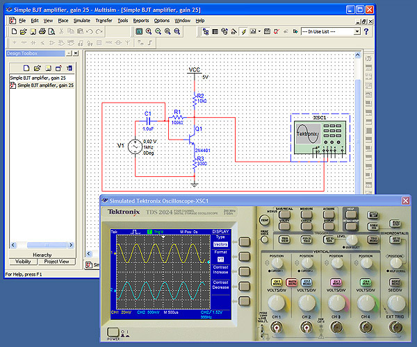
Multisim also includes configurations to automate creating synthesizable and implementable designs for the DEFB.įigure 1. You can use Multisim to create specialized schematics that describe the logic of a PLD, such as the FPGA on the NI Digital Electronics FPGA Board (DEFB).


 0 kommentar(er)
